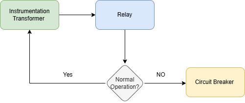
Figure (1) Basic Functionality of a power system protection system
The power system is one of the most crucial systems in operation today. Power engineers design, operate, and maintain the system with careful consideration to minimize the occurrence of faults; however, risks cannot be entirely eliminated.
Power system faults are abnormal conditions that disrupt the normal operation of electrical equipment and networks. During normal operation, power systems maintain specific parameters: voltage levels (typically 120V/240V for residential systems in North America, or 230V/400V in Europe) and frequency (60Hz in North America, 50Hz in most other regions). While current levels vary based on load demands, utilities and system operators establish expected ranges for normal operation, which serve as baselines for fault detection.
Faults can be classified based on their nature, location, and impact. The power grid operates in three phases, and the types of faults in such a system include:
Symmetrical Faults: These are rare but severe faults that affect all three phases equally, such as a three-phase short circuit.
Unsymmetrical Faults: These are more common and affect one or more (but not all) phases. Examples include:
Since single-line-to-ground faults account for over 80% of all occurring faults, this introduction simplifies the discussion by reducing the power system to a single phase. Protection elements are then defined accordingly. In a single-phase context, faults can be further categorized as follows:
1. Short Circuit Faults
A short circuit is defined as a low-impedance path that causes an excessive flow of current. These faults can occur in different forms:
💡 Key Insight: Short-circuit currents can be several orders of magnitude greater than nominal operating currents. If not cleared quickly, they can cause severe thermal damage to equipment, melting conductors, or even leading to fires.
⚠️ Note: Due to the rotational inertia of power generators, they cannot instantly disconnect during a fault. Instead, faulted regions must be isolated by protective devices such as circuit breakers and relays.
2. Open Circuit Faults
An open circuit fault occurs when a break in the conductor prevents current from flowing. This can happen due to:
Open circuit faults can lead to voltage imbalances, overloading of other phases, or inefficient power transfer.
3. Voltage-Based Faults
Voltage deviations from the nominal operating level can cause major disruptions in power systems. These include:
Overvoltage: Voltage exceeds the rated level for an extended period. Causes include:
⚠️ Overvoltage can cause insulation breakdown and damage sensitive electronic equipment.
Undervoltage (Brownout): Voltage drops below the rated level for an extended period. Causes include:
💡 Undervoltage can lead to inefficient operation, increased heat generation in motors, and system instability.
Voltage Swells: Temporary voltage increases lasting milliseconds to seconds. Causes include:
These can cause disruptions in control systems and sensitive electronics.
⚠️ Left undetected, faults can escalate into equipment damage, safety hazards (fires, electrocution), or cascading outages. This is why power system protection is critical.
As defined by J. Lewis Blackburn, a pioneer in the field:
“Power system protection is the science, skill, and art of applying and setting protective relays and/or fuses to provide maximum sensitivity to faults and undesirable conditions while avoiding operation under all permissible or tolerable scenarios.”
Modern protection systems rely on devices like circuit breakers, relays, and surge arrestors to detect anomalies, isolate faulted sections within milliseconds, and restore normal operation.
✅ By combining rapid response with layered redundancy, engineers safeguard both infrastructure and end-users from the cascading consequences of faults.
Modern protection systems rely on devices like circuit breakers, relays, and surge arrestors to detect anomalies, isolate faulted sections within milliseconds, and restore normal operation. By combining rapid response with layered redundancy, engineers safeguard both infrastructure and end-users from the cascading consequences of faults.
The basic components of power system protection are:
Figure (1) Basic Functionality of a power system protection system
As shown in Figure 1, the instrument transformers are used to measure currents. These continuously feed the information to the relays, and the relay being the brain of the operation, based on preset values is able to detect abnormal operation and trip the circuit through the circuit breaker.
The following diagram illustrates these connections in a typical single-phase system as applied to overcurrent protection:
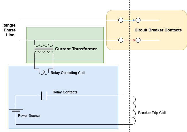
Figure (2) Single Phase power system protection operation
INSTRUMENT TRANSFORMERS:
These are either voltage or current transformers that transform very high currents and voltage to proportionally lower values for measurement, they also provide isolation from the main circuit to allow personnel working with relays to work in a much safer environment, lowering the current and voltages enables use of smaller simpler relays to allow for less expensive components.
RELAYS:
Relay technology has evolved dramatically over the past century, progressing from electromechanical designs in the early 1900s to solid-state relays in the 1970s and microprocessor-based relays like Schweitzer Engineering Laboratories’ (SEL) pioneering model in 1982. Today’s advanced digital relays integrate machine learning and real-time analytics—but to grasp their core function, we must start with the foundational principles of electromechanical relays.
At its core, an electromechanical relay operates based on the principles of electromagnetism. Here's a step-by-step breakdown of its operation:
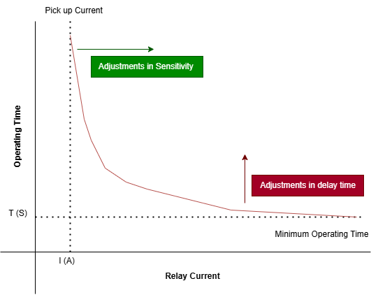
Figure (3) Typical relay curve showing how sensitivity (Pin adjustment) and delay time (Knob adjustment) affect the operation of the relay
While electromechanical relays laid the groundwork, modern systems demand faster, more precise protection:
Relays are the first line of defense in power systems. By isolating faults within milliseconds, they prevent equipment damage, fires, and cascading blackouts. As Blackburn’s definition emphasizes, their role isn’t just to react—it’s to balance sensitivity and selectivity, ensuring minimal disruption to the broader grid.
CIRCUIT BREAKERS:
Circuit breakers are automatic switches designed to disconnect a circuit during faults, preventing equipment damage and fires. While relays detect abnormalities, circuit breakers act as the "muscle" that physically interrupts current flow. To appreciate modern advancements, we first explore the foundational design of miniature circuit breakers (MCBs), commonly used in homes and commercial buildings.
A circuit breaker operates using two primary mechanisms, combined with critical arc containment technology:
Arc Containment: When contacts separate, ionized gas forms an arc, reaching temperatures over 20,000°C. Arc chutes (stacked insulated metal plates) split and cool the arc, while gases vented from insulating materials (e.g., thermoset plastics) deionize the path, extinguishing the arc.
Circuit breakers come in various types, each designed for specific applications. Miniature Circuit Breakers (MCBs) are used in homes and commercial buildings for low-voltage protection, while Molded Case Circuit Breakers (MCCBs) handle higher currents in industrial settings. Air Circuit Breakers (ACBs) are found in main power distribution systems, and Vacuum Circuit Breakers (VCBs) are used for medium-voltage applications due to their durability. For high-voltage transmission, SF₆ Circuit Breakers provide excellent arc suppression. These breakers follow international standards like IEC 60898-1, IEC 60947-2, and IEEE C37.13, ensuring safety and reliability. Many modern systems, including those by manufacturers such as Schneider Electric, ABB, and CBI-electric, now feature smart monitoring and remote control for improved efficiency.
Power system protection is the backbone of modern electrical infrastructure, ensuring reliability, safety, and efficiency. As power systems continue to evolve—with the integration of renewable energy sources, smart grids, and advancements in transmission technologies—the role of protection systems becomes even more critical. The advent of DC circuit breakers , designed to handle high-speed fault interruption in direct current (DC) systems, marks a significant milestone in this evolution. These breakers are essential for emerging applications such as HVDC (High Voltage Direct Current) transmission lines and DC microgrids, addressing challenges unique to DC systems like arc extinction and rapid fault clearing. Looking ahead, power system protection will increasingly rely on intelligent devices, real-time analytics, and predictive maintenance to enhance performance and adapt to dynamic grid conditions. By embracing these innovations, we can build resilient power systems capable of meeting future demands while safeguarding both human lives and critical infrastructure.
Which three components make up the basic protection system?
Click the button below to reveal the correct answer:
Correct Answer: A) Instrumentation Transformer; Relay; Circuit Breaker
Explanation:
- Instrumentation Transformers: These include current transformers (CTs) and potential transformers (PTs), which scale down high currents and voltages for safe measurement by relays. - Relays: Act as the "brain" of the protection system, detecting abnormal conditions and initiating actions based on predefined settings. - Circuit Breakers: Serve as the "muscle," physically interrupting the circuit during faults to protect equipment and personnel.About Disconnectors:
Disconnectors, also known as isolators, are mechanical switches used to isolate sections of the power system for maintenance or operational purposes. Unlike circuit breakers, disconnectors are not designed to interrupt fault currents. If a disconnector is operated under fault conditions, it may lead to the formation of arcs due to the high current flow, potentially causing damage to equipment or posing safety risks. Therefore, disconnectors should only be used when the circuit is de-energized or under normal load conditions.